- 您现在的位置:买卖IC网 > Sheet目录2006 > LTC2382HMS-16#PBF (Linear Technology)IC ADC 16BIT 1CH 500KSPS 16-MSOP
LTC2382-16
18
238216f
TIMING DIAGRAM
OVDD
238216 F14a
CONVERT
IRQ
DATA IN
DIGITAL HOST
CLK
CNV
LTC2382-16
BUSY
SDO
B
SCK
RDL/SDI
CNV
LTC2382-16
SDO
A
SCK
RDL/SDI
CHAIN
OVDD
CHAIN
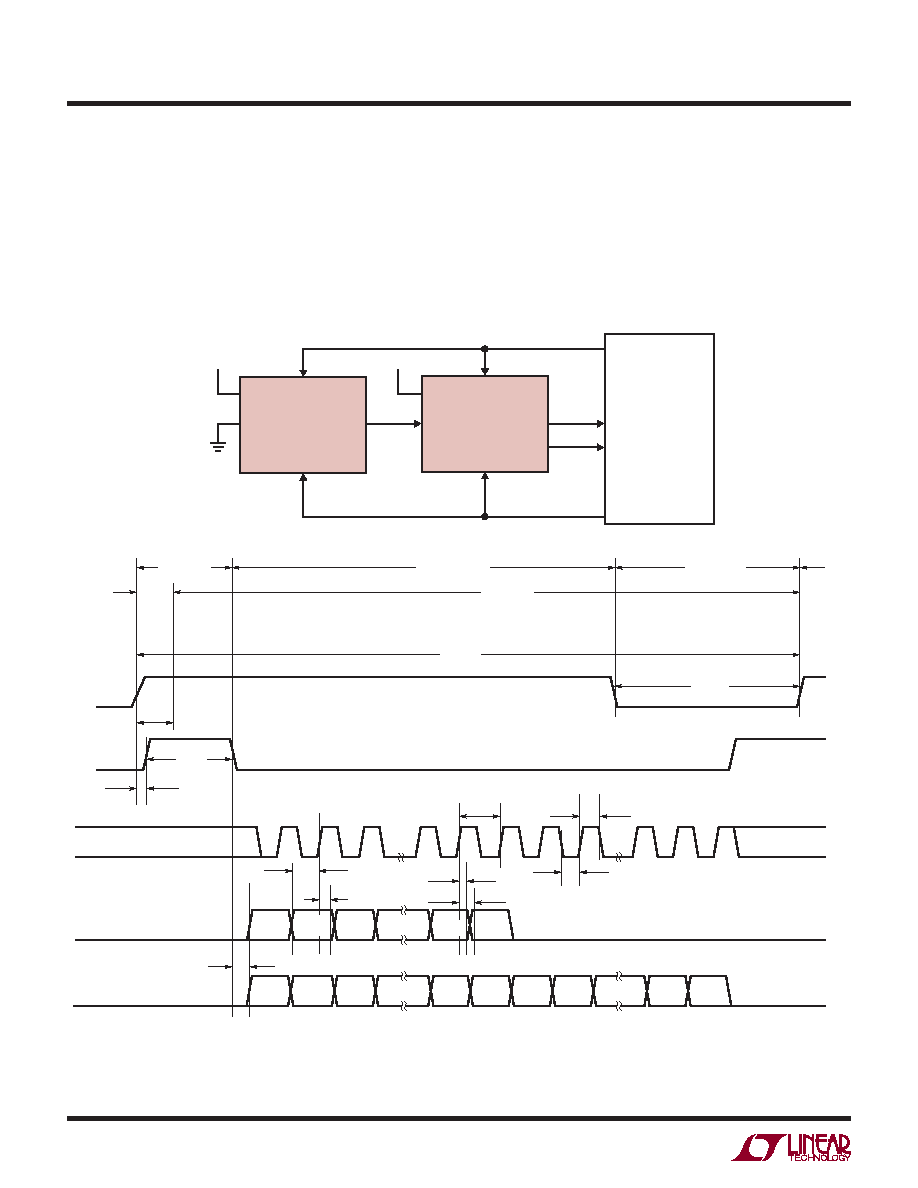
When CHAIN = OVDD, the LTC2382-16 operates in Chain
Mode. In Chain Mode, SDO is always enabled and RDL/SDI
serves as the serial data input pin (SDI) where daisychain
data output from another ADC can be input.
This is useful for applications where hardware constraints
may limit the number of lines needed to interface to a large
number of converters. Figure 14 shows an example with
two daisy chained devices. The MSB of converter A will
appear at SDO of converter B after 16 SCK cycles. The
MSB of converter A is clocked in at the SDI/RDL pin of
converter B on the rising edge of the first SCK.
Figure 14. Chain Mode Timing Diagram
238216 F14
D0A
D1A
D14A
D15A
D13B
D14B
D15B
SDOB
SDOA = RDL/SDIB
RDL/SDIA = 0
D0B
D1B
D13A
D14A
D15A
D0A
D1A
12
3
14
15
16
17
18
30
31
32
tDSDOBUSYL
tSSDISCK
tHSDISCK
tBUSYLH
tCONV
tHOLD
tHSDO
tDSDO
tSCKL
tSCKH
tSCKCH
tCNVL
tCYC
CONVERT
ACQUIRE
POWER-DOWN
POWER-UP
SCK
CNV
BUSY
CHAIN = OVDD
发布紧急采购,3分钟左右您将得到回复。
相关PDF资料
LTC2383HMS-16#PBF
IC ADC 16BIT 1CH 1MSPS 16-MSOP
LTC2393IUK-16#TRPBF
IC ADC 16BIT SER/PAR 1M 48-QFN
LTC2410IGN#TRPBF
IC ADC 24BIT DIFF INP/REF 16SSOP
LTC2411-1IMS#TRPBF
IC A/DCONV DIFF INPUT&REF 10MSOP
LTC2418IGN#TRPBF
IC ADC 24BIT DIFF INPUT 28SSOP
LTC2431IMS#TRPBF
IC ADC 20BIT DIFFINPUT/REF10MSOP
LTC2433-1IMS#TRPBF
IC ADC DIFF 16BIT 3WIRE 10-MSOP
LTC2435CGN#TRPBF
IC ADC DIFF I/REF 20BIT 16-SSOP
相关代理商/技术参数
LTC2382HMS-16#TRPBF
功能描述:IC ADC 16BIT 1CH 500KSPS 16-MSOP RoHS:是 类别:集成电路 (IC) >> 数据采集 - 模数转换器 系列:- 标准包装:1,000 系列:- 位数:12 采样率(每秒):300k 数据接口:并联 转换器数目:1 功率耗散(最大):75mW 电压电源:单电源 工作温度:0°C ~ 70°C 安装类型:表面贴装 封装/外壳:24-SOIC(0.295",7.50mm 宽) 供应商设备封装:24-SOIC 包装:带卷 (TR) 输入数目和类型:1 个单端,单极;1 个单端,双极
LTC2382IDE-16#PBF
功能描述:IC ADC 16BIT 1CH 500KSPS 16-DFN RoHS:是 类别:集成电路 (IC) >> 数据采集 - 模数转换器 系列:- 标准包装:1,000 系列:- 位数:12 采样率(每秒):300k 数据接口:并联 转换器数目:1 功率耗散(最大):75mW 电压电源:单电源 工作温度:0°C ~ 70°C 安装类型:表面贴装 封装/外壳:24-SOIC(0.295",7.50mm 宽) 供应商设备封装:24-SOIC 包装:带卷 (TR) 输入数目和类型:1 个单端,单极;1 个单端,双极
LTC2382IDE-16#TRPBF
功能描述:IC ADC 16BIT 1CH 500KSPS 16-DFN RoHS:是 类别:集成电路 (IC) >> 数据采集 - 模数转换器 系列:- 标准包装:1,000 系列:- 位数:12 采样率(每秒):300k 数据接口:并联 转换器数目:1 功率耗散(最大):75mW 电压电源:单电源 工作温度:0°C ~ 70°C 安装类型:表面贴装 封装/外壳:24-SOIC(0.295",7.50mm 宽) 供应商设备封装:24-SOIC 包装:带卷 (TR) 输入数目和类型:1 个单端,单极;1 个单端,双极
LTC2382IMS-16#PBF
功能描述:IC ADC 16BIT 1CH 500KSPS 16-MSOP RoHS:是 类别:集成电路 (IC) >> 数据采集 - 模数转换器 系列:- 标准包装:1,000 系列:- 位数:12 采样率(每秒):300k 数据接口:并联 转换器数目:1 功率耗散(最大):75mW 电压电源:单电源 工作温度:0°C ~ 70°C 安装类型:表面贴装 封装/外壳:24-SOIC(0.295",7.50mm 宽) 供应商设备封装:24-SOIC 包装:带卷 (TR) 输入数目和类型:1 个单端,单极;1 个单端,双极
LTC2382IMS-16#TRPBF
功能描述:IC ADC 16BIT 1CH 500KSPS 16-MSOP RoHS:是 类别:集成电路 (IC) >> 数据采集 - 模数转换器 系列:- 标准包装:1,000 系列:- 位数:12 采样率(每秒):300k 数据接口:并联 转换器数目:1 功率耗散(最大):75mW 电压电源:单电源 工作温度:0°C ~ 70°C 安装类型:表面贴装 封装/外壳:24-SOIC(0.295",7.50mm 宽) 供应商设备封装:24-SOIC 包装:带卷 (TR) 输入数目和类型:1 个单端,单极;1 个单端,双极
LTC2383CDE-16#PBF
功能描述:IC ADC 16BIT 1CH 1MSPS 16-DFN RoHS:是 类别:集成电路 (IC) >> 数据采集 - 模数转换器 系列:- 标准包装:1,000 系列:- 位数:12 采样率(每秒):300k 数据接口:并联 转换器数目:1 功率耗散(最大):75mW 电压电源:单电源 工作温度:0°C ~ 70°C 安装类型:表面贴装 封装/外壳:24-SOIC(0.295",7.50mm 宽) 供应商设备封装:24-SOIC 包装:带卷 (TR) 输入数目和类型:1 个单端,单极;1 个单端,双极
LTC2383CDE-16#TRPBF
功能描述:IC ADC 16BIT 1CH 1MSPS 16-DFN RoHS:是 类别:集成电路 (IC) >> 数据采集 - 模数转换器 系列:- 标准包装:1,000 系列:- 位数:12 采样率(每秒):300k 数据接口:并联 转换器数目:1 功率耗散(最大):75mW 电压电源:单电源 工作温度:0°C ~ 70°C 安装类型:表面贴装 封装/外壳:24-SOIC(0.295",7.50mm 宽) 供应商设备封装:24-SOIC 包装:带卷 (TR) 输入数目和类型:1 个单端,单极;1 个单端,双极
LTC2383CDE-16PBF
制造商:Linear Technology 功能描述:ADC 16-Bit 1Msps Low Power SPI DFN16